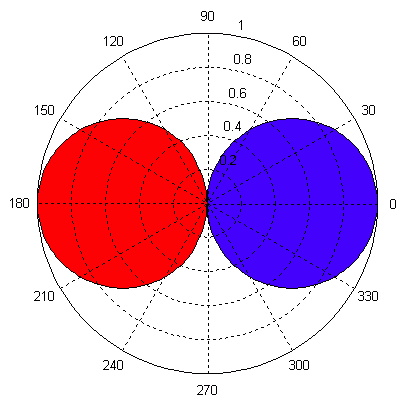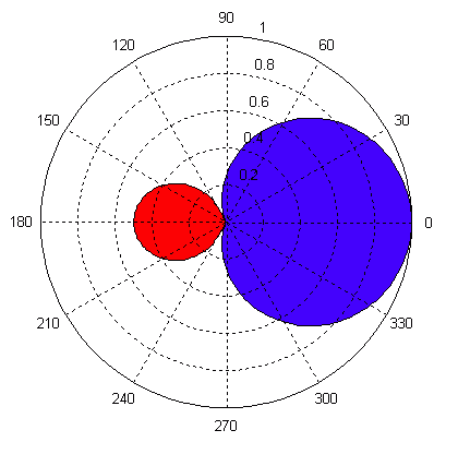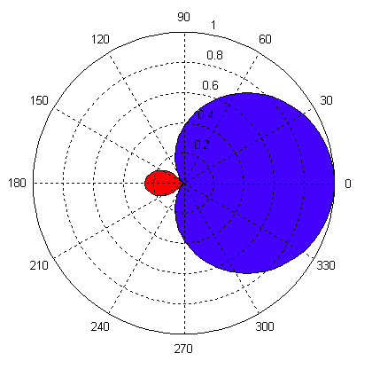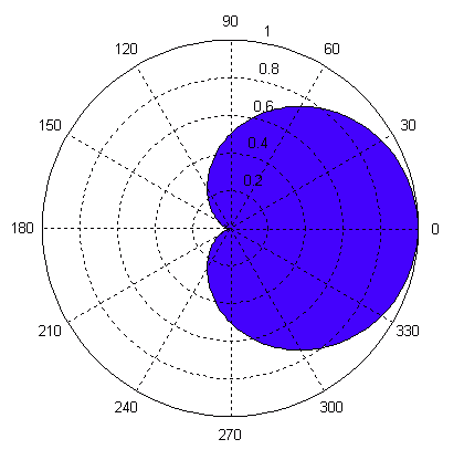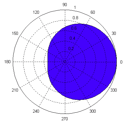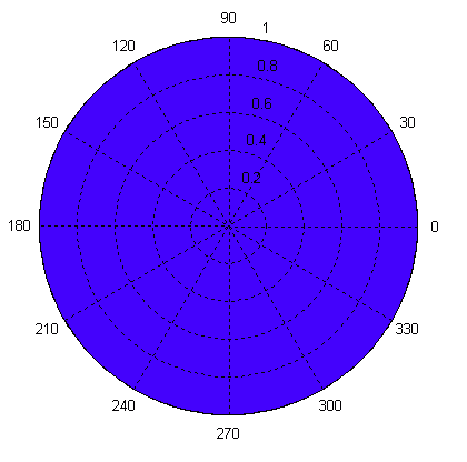
Microphone DirectivityThere are two types of microphones I will address for explaining the topic of microphone directivity. The first is the pressure microphone. This type of mic responds to the pressure of the sound field in which it is placed. The second type is the pressure gradient microphone. This type of mic responds to the pressure gradient, or change in pressure, between two spaced points in a sound field. The construction of a pressure mic is similar to a loudspeaker driver in a closed box. Its directivity pattern is pretty much omni-directional. The construction of a pressure gradient mic is similar to a drum tom head. Its directivity pattern is a figure 8. As one can see, a sound wave hitting the front of the drumhead will cause it to move in one direction. While a wave hitting the rear of the drumhead will cause it to move in the other direction. This represents a reversal in polarity between the front half & the rear half of the pickup pattern. A combination pressure and pressure gradient microphone may be constructed. One possible method is to combine them acoustically. This construction will be somewhat like a vented loudspeaker enclosure with the vent on the back of the enclosure or a drum tom. The drumhead represents the microphone diaphragm. The sound wave hits the front of the diaphragm. It must then travel a distance the length of the drum shell to reach the back of the diaphragm. This length of the drum shell helps to determine the directivity pattern of the microphone. If the drum shell is infinitely small, no shell, the mic is omni-directional. As the length of the shell increases the pattern will become cardioid, then super cardioid, then hyper cardioid, and eventually figure 8. As I am not a microphone engineer, all of the above is a gross simplification. However, the physical principals are sound (no pun intended). 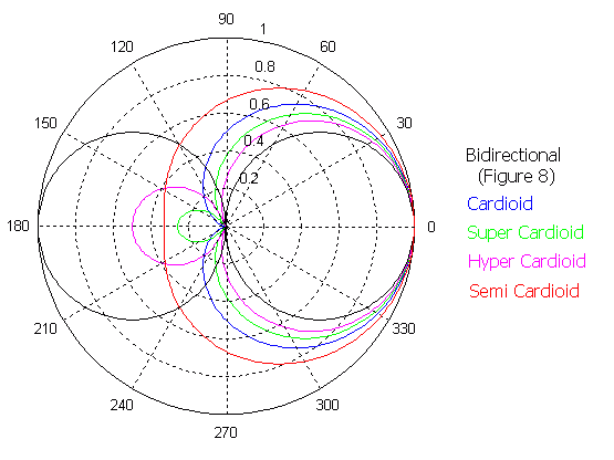
A combination pressure and pressure gradient microphone may also be constructed electrically. In this method each of the two types are present in the microphone housing. The output of each type is mixed together. The level of one type relative to the other will determine the combined directivity pattern. Let R1 represent the level of the non-directional mic (omni) and R2 represent the level of the bidirectional mic (figure 8). |
||||||||||||
|
||||||||||||
|
The polarity of the pickup patterns is illustrated below. Blue shading represents positive polarity. The signal transduction performed by the microphone preserves the absolute polarity of the source when it is in this area. Red shading represents a polarity reversal. The signal transduction performed by the microphone reverses the absolute polarity of the source when it is in this area. |
||||||||||||
|
|
||||||||||||
|
||||||||||||
|
|
| Excelsior Audio Labs |
